Device
1. Overview
![]()
This component allows the user to add a single device model (.sdm) to a circuit, configure its contact orientation and naming, and define how the 2‑dimensional device is interpreted in 3‑dimensional space during simulation.
2. Parameters
| Name | Description | Unit |
|---|---|---|
Name | A unique identifier for the device in the circuit. | - |
File Name | The file path name of the .sdm model. | - |
Type | The geometric interpretation type. Options: [Linear, Cylindrical] Linear assumes the device extends uniformly in the z‑direction (Cartesian). Used for MOSFETs, diodes, IGBTs, planar structures, etc. Cylindrical interprets the 2D cross‑section as a radial slice that is revolved around the X axis, forming an axis‑symmetric 3D device. Used for cylindrical diodes, radial sensors, coaxial structures, etc | - |
Scaling Factor | For linear devices, this defines the physical depth (z‑extent) of the device used in 3D calculations. | cm |
X Origin | For cylindrical devices, this defines the radial origin (the axis of revolution) around which the 2D cross‑section is rotated. | cm |
3. Usage Instructions
The device component is added the same way a standard component.
For instructions on adding a component to the simulation circuit, click here.
Once the device has been placed in the circuit, the user must associate it with a Single Device Model (.sdm) file.
- Click
Get .sdm File.
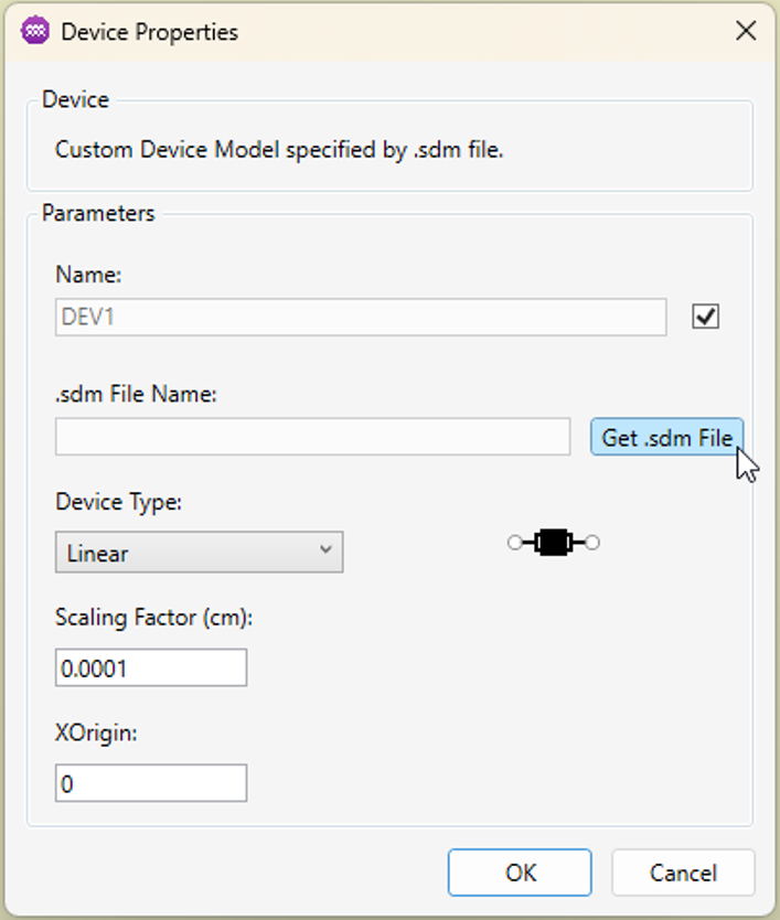
- A file dialog will appear. Select the .sdm file you want this device instance to use.
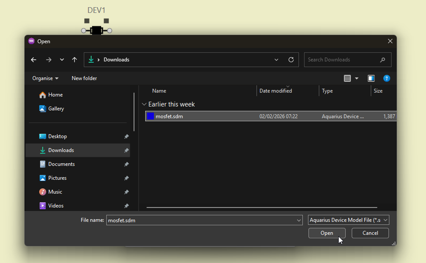
The .sdm file must reside in the same directory as the .sol file produced by the Circuit Simulator. Ensure the directory structure is correct before running a simulation.
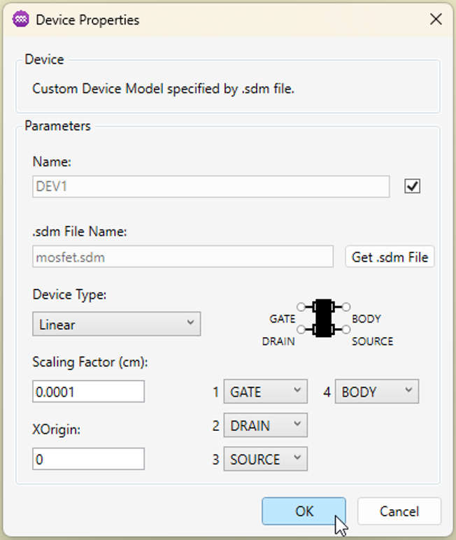
- Review and reorder device contacts. After loading the model, the device contacts will appear in the properties panel. Use the dropdown menus to reorder the contacts so that they match the circuit topology you require.
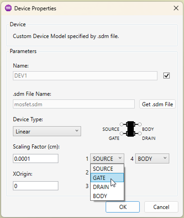
-
Specify the geometric interpretation. Choose the Type (Linear or Cylindrical) and enter the appropriate parameter:
- Scaling Factor (for linear devices)
- X Origin (for cylindrical devices)
-
Click
OK. The configured device will be added to the circuit diagram and linked to the selected model file.